
Chapter-6 Electromagnetic induction class 12 notes (Completes Notes)
According to the CBSE syllabus, Unit-4 Electromagnetic induction class 12 and alternating currents carry 8 marks in the CBSE board exam. CBSE Digital Education provides the best notes of physics class 12 chapter-6 that are per the latest syllabus of CBSE syllabus.
Let’s Start the definition of electromagnetic induction class 12. In this article, all the concepts of this chapter “electromagnetic induction” are discussed. Read and enjoy amazing articles.
What is electromagnetic induction?
When magnetic flux over a conducting loop is change then an emf develops in this loop. This emf is called induced emf and this phenomenon is called electromagnetic induction.
Magnetic Flux
The total number of magnetic field lines crossing through any surface normally, when it is placed in a magnetic field is called magnetic flux of that surface.
dØ = B x ds = B x ds x cos θ
- Its SI unit is Weber (Wb)
One Weber = 1 Tesla x 1 metre2
- Its dimensional formula = [ML2T-2A-1]
- Its CGS unit is Maxwell (Mx)
One Maxwell = 1 gauss x 1 cm2
- The relation between Weber and Maxwell
1 Weber = 108 Maxwell
Faraday’s Experiments
Faraday performed an experiment with the help of a magnet and coil. During this experiment, he found how emf is induced in the coil particularly when flux linked with it changes.
Relationship between induced e.m.f. and flux when a bar magnet is held stationary or moved close or away from the coil.
[wptb id=1451]
In this Faraday’s experiment, Faraday concluded that whenever there is a relative motion between the conductor and a magnetic field, the flux linkage with a coil changes, and this change in flux induces a voltage across a coil.
Faraday’s Laws of Electromagnetic Induction class 12
- Faraday’s First Law
According to Faraday’s 1st law, whenever the magnetic flux linked with a circuit changes, an emf is always induced in it or whenever a conductor cuts magnetic flux, an emf is induced in that conductor.
- Faraday’s Second Law
The magnitude of the induced electromotive force (emf) is equal to the rate of change of flux linkages.
Suppose a coil has N turns and flux through its changes from the initial value of Ø1 Weber to the final value of Ø2 webers in time t seconds. But as flux linkages equal to the product of the number of turns by the flux linked with the coil,
Initial flux linkages = NØ1
Final flux linkages = NØ2
Induced emf, e = (NØ1 – NØ2) /t Volt
c = (N-ΔΦ)/t
Putting the above equation in differential form, we get
e = θ/dt (NΦ) Volt
e = – N θ/dt Volt
Usually, a minus sign is given to the right-hand side expression to signify the fact that the induced e.m.f. sets up a current in such a direction that the magnetic effect produced by it opposes the very cause producing it.
Lenz’s law
The law considered analogous to Newton’s third law in classical mechanics is the third law of electromagnetic induction. It is named after Russian physicist Heinrich Lenz who formulated it in 1834.
This law states that the direction induced in a conductor by changing the magnetic field due to Faraday’s law of induction will be such that it creates a field that opposes the change that produced it.
ε = – dØ/dt
Lenz’s law is shown by the negative sign in Faraday’s law of induction which indicated that the induced voltage (ε) and the change in magnetic flux (dØ) have the opposite signs. It is a qualitative law that specifies the direction of induced current but says nothing about its magnitude.
When the magnetic flux linking a coil increases, the direction of current in the coil will be such that it will oppose the increase in flux and thus the induced current will produced its flux in a direction as shown below (using right- hand thumb rule).
If magnetic flux linking a coil is decreasing, the flux produced by the current in the coil is such that it will aid the main flux and hence the direction of current is shown below:
Lenz’s law and the law of conservation of energy
When a magnet is moved towards or away from a closed coil, the induced current always opposes the motion of the magnet, as predicted by Lenz’s law. For example, if the north pole of a magnet is brought closer to a coil, its face towards the magnet develops north polarity and hence repels the North Pole of the magnet. Work has to be done in moving the magnet closer to the coil against this force of repulsion.
Similarly, when the North Pole of the magnet is moved away from the coil, its face towards the magnet develops South Pole polarity and thus attracts the north pole of the magnet. This work has to be done in moving the magnet away from the coil against this force of attraction. It is this work done against the force of repulsion or attraction that takes the form of electric energy in the form of induced current.
Suppose that Lenz’s law is not valid. Hence the induced current flows through the coil in a direction opposite to one dictated by Lenz’s law of electromagnetic induction. The resulting force on the magnet makes it move faster and faster, i.e, the magnet gains speed and hence kinetic energy without expending an equivalent amount of energy. This sets up a perpetual motion machine, violating the law of conservation of energy. This Lenz’s law is valid and is a consequence of the law of conservation of energy.
Application of Lenz’s law
The main application or uses of Lenz’s law are the following:
- It is used in electromagnetic braking and induction cooktops.
- This law indicates that the induced e.m.f. and the change in flux have opposite signs which provide a physical interpretation of the choice of sign-in Faraday’s law of induction.
- Lenz’s law is used for understanding the concept of stored magnetic energy in an inductor.
- Lenz’s law is applied to electric generators. When current is induced in a generator, the direction of this induced current is such that it opposes and causes rotation of generator and hence the generator requires more mechanical energy. It also provides back e.m.f. in case of electric motors.
Fleming’s Right-Hand rule
According to Fleming Right-Hand rule, if the right hand is stretched out with the first finger, second finger, and the thumb at the right angle to one another and if the forefinger represents the direction of the line of force and the thumb points in the direction of motion or applied force, then the second finger will point in the direction of the induced current.
Eddy current
If a piece of metal is placed in a varying magnetic field or rotated with speed in a uniform magnetic field, then the induced currents set up in the piece are like a whirlpool of air known as eddy current.
Application of Eddy Currents
Application of eddy currents is used in the following devices:
- Electromagnetic damping: When a current is passed through a galvanometer, its coil suffers few oscillations before coming to rest in the final position. As the coil moves in the magnetic field, the induced current is sent in the coil which opposes its motion. The oscillations of the coil are damped. This is known as electromagnetic damping. It can be further increased by winding the coil on a light copper or aluminum frame. Since the frame moves in the magnetic field, eddy currents are set up in the frame which resists the motion of the coil. This is how a galvanometer is rendered dead beat that is coil does not oscillate it deflects and stays in the final position immediately.
- Induction furnace: If a metal specimen is placed in a rapidly changing magnetic field, very large eddy currents are set up. The heat produced is sufficient to even melt the metallic substance. This process is used in the extraction of some metals from their ores.
- Electric brakes: A strong magnetic field is applied to the rotating drum attached to the wheel. Eddy currents set up in the drum suck a torque on the drum so as to stop the train.
Notes of Electromagnetic Induction Class 12 Notes
Self-Induction
The phenomenon of production of induced emf in a circuit due to change in the current flowing on its own is known as self-induction.
In other words, when the electric current in a conducting loop is changed then the magnetic field associated with these current changes, and hence magnetic flux through the conducting loops changes. Due to a change in magnetic flux and emf develops in the conducting loop. This emf is called self-induced emf and this phenomenon is called self-induction.
Self-inductance depends on the shape and size of the conducting loop, also on the medium.
- The SI unit of self-induction = Henry
- Its dimensional formula = [ML2T-2A-2]
Phenomena associated with self-induction
Sparking: The break of a circuit is very sudden. If the circuit is switched off, a largely self-induced emf is set up in the circuit in the same direction as the original emf. This causes a big spark across the switch.
Non-inductive winding: In post office boxes and resistance boxes, different resistance coils have to be used. Here the wire is first doubled over itself and then wound in the form of a coil over a bobbin. The inductive effects of the 2 halves of the wire, being in opposite directions and cancel each other. The net self-inductance of the coil is minimum. Such a winding of coils is called non-inductive winding.
Mutual Induction
The phenomena of production of induced emf in a circuit due to the change in magnetic flux in its neighboring circuit is known as mutual induction.
- The unit of coefficient of mutual induction = Henry
- Its dimensional formula = [ML2T-2A-2]
- The coefficient of mutual induction depends on the geometry of two coils, the distance between them, and the orientation of the coils.
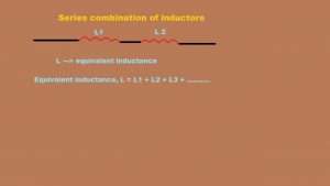
Grouping of Inductors(coils)
(a) When two coil of inductances L1 and L2 are connected in series and the coefficient of coupling k = 0 as in series, then L = L1 + L2
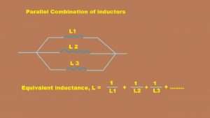
(b) When two coil of inductances L1 and L2 are connected in parallel and the coefficient of coupling k = 0 as in parallel, then
1/L = 1/L1 +1/L2
If the coefficient of coupling is K = 1, then
1. In Series:
(a) If the current in two coils are in the same direction, then
L = L1 + L2 + 2M
(b) If the current in two coils are in opposite directions, then
L = L1 + L2 – 2M
2. In Parallel
(a) If the current in two coils are in the same direction, then
L = (L1L2 – M2)/(L1+L2+2M)
L = (L1L2 – M2)/(L1+L2-2M)
Frequently Asked Question (FAQ) of electromagnetic induction class 12
- What is motional emf?
Answer: When a conducting wire moves in a magnetic field then due to magnetic force positive charge is accumulated at one end and a negative charge is accumulated at its other ends due to these charges electric field develops in the wire and thus potential difference develops between the two ends of conducting wire. This potential difference is known as motional emf.
Let a conducting wire of length (l) moves with velocity (v) in a uniform magnetic field (B).
qE = q x V x B x Sin90
E = V X B
ε = E x L
ε = V x B x L
Motional emf = B x L x V
- What is the average emf?
Answer: It is defined as the net change in magnetic flux divided by total time.
- What is energy density?
Answer: Magnetic field energy per unit volume is defined as energy density.
- Difference between electric flux and magnetic flux.
Answer: Electric flux is defined as the number of field lines or the concentration of field lines of an electric field perpendicular to a surface.
Magnetic flux: It is quite similar to electric flux with the number of magnetic field lines or the concentration of magnetic field lines perpendicular to a given surface. It is because monopoles, i.e, only North or only South poles are not known to exist. The magnetic flux through any closed surface is always zero as the number of field lines going into the surface is equal to the number of imaginary field lines coming out.
I hope you like this post ” Electromagnetic induction class 12″. Comment below for other important chapters of class 12.